Needing OEM support from the conception and design stage to the delivery of the final product and commissioning, the client chose SAGE Automation to deliver an end-to-end OEM solution to enable the in-house capability of measuring the torque, power, current, and engine speed of electric drive drill rigs.
Utilising its own supply chain, SAGE designed, manufactured, and commissioned a purpose-built electric dynamometer and control system cabinet.
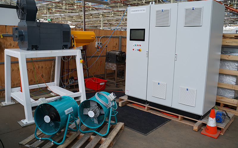
 The SAGE-built electric dynamometer (back left) and control system cabinet (right), together with two fans used within the resistor bank (front left)
Concept
The concept phase of this project required extensive research and development, given the significant power (150kW) needed to deliver the client outcomes for the electric dynamometer.
SAGE’s product development team conducted in-house research and development, collaborating with integration and implementation solution partner, Siemens, mechanical design and manufacture partner, Cornell Design, and resistor specialists, Fortress Resistors, to develop the framework for the solution.
The framework required the following components to be designed and manufactured:
- Electric dynamometer
- PLC and HMI
- Cabinet
- Resistor bank
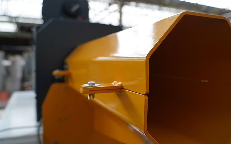
 A close-up, frontal view of the electric dynamometer.
During the conceptual phase, it became apparent that the power coming into the client’s site was insufficient to generate back into the grid. The solution was to dissipate the energy through heat generation in the resistor bank, requiring two integrated fans to mitigate overheating.
Design
With the conceptual framework in place, SAGE could begin the design phase. This involved firming up the concept and relying on SAGE’s engineering expertise to ensure the right parts and specifications were in place to manufacture a physical solution.
As part of the solution development, SAGE was responsible for the manufacturing, electrical design, mechanical design, PLC and HMI design, Factory Acceptance Testing (FAT) and Site Acceptance Testing (SAT). Siemens was the chosen technology for the dynamometer control system, and it incorporates the following:
- Siemens SIMATIC ET 200SP - CPU 1510SP F-1 PN (PLC)
- Siemens MTP-1500 Unified Comfort Panel (HMI)
- Siemens SINAMICS S120 control unit CU320-2 PN (Drive Control Unit)
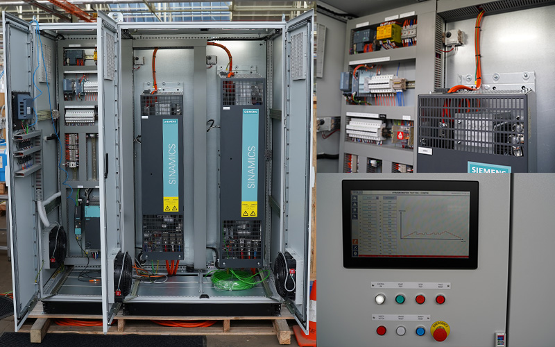
 The purpose-built cabinet features Siemens technology and a connected HMI for real-time monitoring and analysis.
Using the HMI, the operator can oversee the system and drill performance through the integrated screens. The system status can be monitored visually from the home screen, while detailed alarms are viewed in the alarms tab.
The drill performance can be monitored via the HMI’s ‘trends’ view, which shows live trends of either the torque, power, current or speed – based on real-time measured outputs from the drill – against a user-defined target (setpoint) for the drill to achieve.
The mode of operation for the dynamometer allows for manual or automatic control, enabling the operator to configure torque setpoints manually or automatically through recipe configurations.
The automated recipes enable the operator to create user-made torque setpoint configurations for the system to output sequentially.
To assist with visualising the torque setpoint profile, a live trend generates alongside the data to illustrate the torque step outputs throughout the duration of the operation.
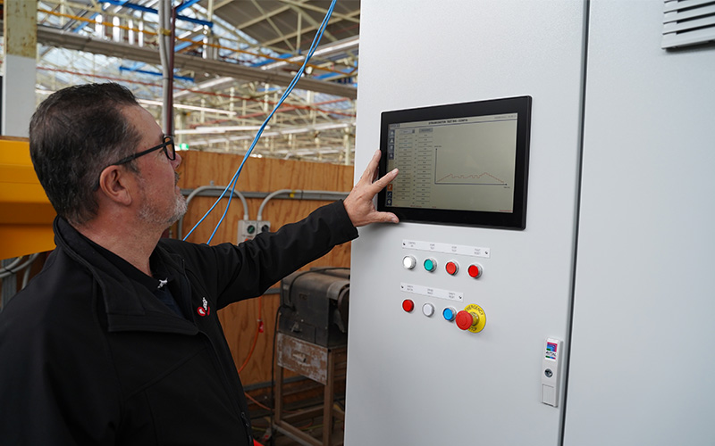
 A SAGE engineer testing a configured recipe using the HMI.
To ensure the data from the dynamometer can be analysed and manipulated, the PLC automatically tabulates, exports and stores the data to an external storage device at the end of every operation. The data is sampled every 500ms and provides the timestamp, tag name and corresponding value.
Due to the advanced capabilities of the Siemens Unified Comfort Panel, the system can be accessed and controlled remotely. This connection is IP and password secured and can only operate upon pressing the SAFETY RESET pushbutton from the physical I/O panel.
Manufacture and commissioning
The manufacture of the electric dynamometer, control panel, resistor bank, and cabinet was completed in-house at SAGE’s advanced manufacturing facility within the South Australian headquarters. The mechanical design and manufacture of the motor frame and coupling were completed by Cornell Design.
FAT was completed in Tonsley, South Australia. SAT was completed by WA-based SAGE engineers on-site in Western Australia.
 The SAGE-built electric dynamometer (back left) and control system cabinet (right), together with two fans used within the resistor bank (front left)
 A close-up, frontal view of the electric dynamometer.
 The purpose-built cabinet features Siemens technology and a connected HMI for real-time monitoring and analysis.
 A SAGE engineer testing a configured recipe using the HMI.


